

Automatic Transfer Switch ATS: Complete Guide
A severe storm rolls through Pennsylvania, the utility drops out, and the house goes quiet. The kitchen lights disappear, the refrigerator starts warming, the internet equipment shuts down, and anyone using a portable generator now faces a dangerous question: which circuits should be energized, and how can they be connected without backfeeding the utility?
An automatic transfer switch ATS removes that manual decision from the outage itself. It monitors the normal power source, starts the standby source when required, and moves selected loads to backup power through a controlled sequence. The equipment looks simple from the outside, but its fault rating, transfer timing, control wiring, and panel compatibility determine whether the system works safely when the grid fails.
Table of Contents
What Happens When the Grid Goes Down - The ATS removes the risky handoff
How an Automatic Transfer Switch Works - The transfer sequence - Why timing matters
Open Transition Versus Closed Transition Transfer - Open transition - Closed transition
ATS Types and Rating Considerations - Common construction types - Rating checklist - Market size does not replace engineering
Installation and Compatibility Essentials - Check the panel before ordering - Verify the control interface - Plan maintenance at installation
Why Specification Errors Cause Real Failures - Four mistakes with predictable consequences - Faster isn't automatically safer
Choosing the Right ATS Solution - Use this decision sequence - Why local experience helps
What Happens When the Grid Goes Down
At first, the outage seems like an ordinary inconvenience. Someone reaches for a flashlight, another person checks the electrical panel, and the generator sits outside waiting to be connected. That plan becomes harder when the refrigerator, heating system, sump pump, medical equipment, security system, or business network all need different priorities.
A portable generator can supply useful backup power, but connecting it incorrectly can energize utility lines and expose workers to serious danger. Manually moving breakers also creates opportunities for the wrong circuits to be energized, the generator to be overloaded, or the system to be left in an unsafe position when utility power returns.

The ATS removes the risky handoff
An ATS sits between the available power sources and the protected loads. In a common standby arrangement, the normal source is utility power and the alternate source is a permanently installed generator. The switch doesn't create electricity. It decides which source is allowed to feed the connected circuits, and it coordinates that decision with the generator controller.
The practical benefit is controlled operation. During a utility failure, the system can detect the problem, request generator startup, wait for acceptable output, and transfer the selected load without asking someone to open the panel during the storm. When utility service returns, the ATS can verify that the normal source has stabilized before returning the load.
Practical rule: An ATS should be treated as part of a complete power system, not as an accessory that can be added to any generator and panel after the fact.
The right design still requires a load assessment and a code-compliant installation. An ATS that is too small, poorly matched to the generator, or installed without proper source isolation won't turn an improvised backup arrangement into a dependable one.
How an Automatic Transfer Switch Works
An ATS acts as the control point between utility power, a standby generator, and the protected loads. It monitors both sources and allows the load to use only the source that meets its programmed voltage, frequency, and timing conditions. The controller also exchanges start and status signals with the generator.
The sequence matters because the switch must protect equipment while preventing the two sources from being connected incorrectly.
The transfer sequence
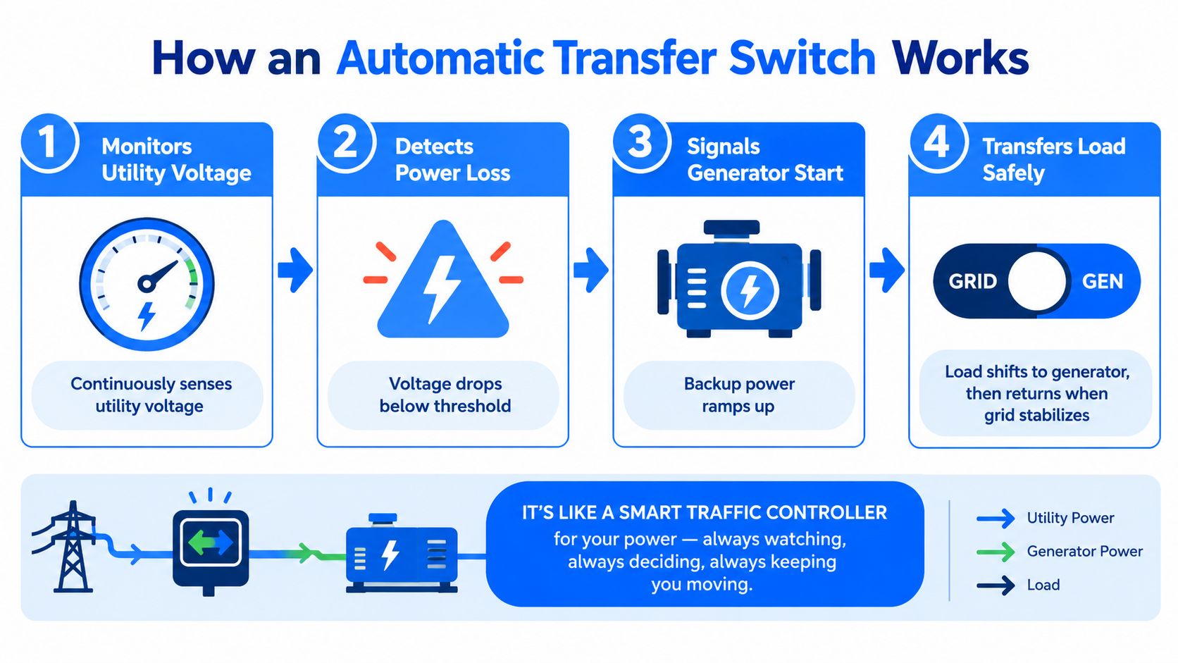
The ATS monitors utility power. Sensing circuits check whether the normal source remains within its configured voltage and frequency range. A brief disturbance may not justify starting the generator, so the controller uses pickup and time-delay settings to separate a sustained failure from a momentary fluctuation.
The controller detects a failed or unacceptable source. If utility power falls outside those limits, the ATS sends a start command through the generator control circuit. The normal source remains isolated from the generator-fed load while the alternate source starts. Correct source isolation and compatible neutral switching are installation details, not optional refinements.
The generator reaches stable output. The engine needs time to run up and produce usable voltage and frequency. The ATS should not place the load on a source that is still accelerating or producing unstable power. Generator capacity, connected load, and the available fault current at the installation also need to align with the switchgear rating.
The switch moves the load. After the generator meets the programmed conditions, the ATS disconnects the protected circuits from utility power and connects them to the generator. In an open-transition arrangement, the sources are separated during the changeover. The panel configuration must match the ATS, including pole count, neutral arrangement, conductor termination, and the equipment's short-circuit withstand rating.
The controller supervises the return. When utility power comes back, the ATS waits for the normal source to stabilize rather than transferring immediately. It then returns the load, allows the generator to complete its cooldown period, and sends the shutdown command.
Why timing matters
A transfer that occurs too quickly can be as problematic as one that takes too long. The generator needs time to establish stable output, while sensitive loads may have limited ride-through capability. The applicable performance framework, UL 1008 transfer-switch requirements, covers automatic, manual, and closed-transition transfer switches up to 1,000 V. Industry references to that standard identify a minimum on-time of 0.167 seconds in each contact position. Published ATS products commonly show total transfer times in the 2 to 6 second range and off-time windows of roughly 0.4 to 1.5 seconds.
Those figures do not guarantee the same result at every site. Generator warm-up settings, controller logic, source conditions, load type, and transition method all affect actual performance. A dependable installation sets timing around the generator and connected equipment, then verifies that the ATS, panel, and protective devices coordinate under the available fault conditions.
Open Transition Versus Closed Transition Transfer
The transition method determines what happens between disconnecting one source and connecting the other. It also affects generator protection, equipment ride-through, control complexity, and project cost.
Open transition
Open transition, also called break-before-make or delay-transfer, disconnects the load from the normal source before connecting it to the alternate source. The load experiences a brief interruption while the ATS changes position.
This is the conventional choice for many homes and small businesses because it provides clear source separation and straightforward operation. Lighting will go out briefly, and some electronic equipment may restart unless it has internal ride-through support or is backed by an uninterruptible power supply. Motors and compressors may also have their own restart behavior, which should be considered during load planning.
The main advantage is simplicity. The ATS doesn't need to parallel the utility and generator, and the system avoids the risk of connecting unsynchronized sources. For general residential backup, that trade-off is often reasonable.
Closed transition
Closed transition, also called make-before-break, briefly overlaps the utility and generator sources during transfer. The goal is to move the load without a noticeable interruption, which can benefit facilities where a brief loss of power would interrupt a process, reset controls, or affect critical operations.
The overlap requires more than a different switch position. The controller must confirm that the two sources are suitable for momentary parallel operation, and the installation must account for synchronization, protection, utility requirements, and the consequences of an abnormal condition. A closed-transition system isn't automatically safer or more reliable just because it reduces the interruption.
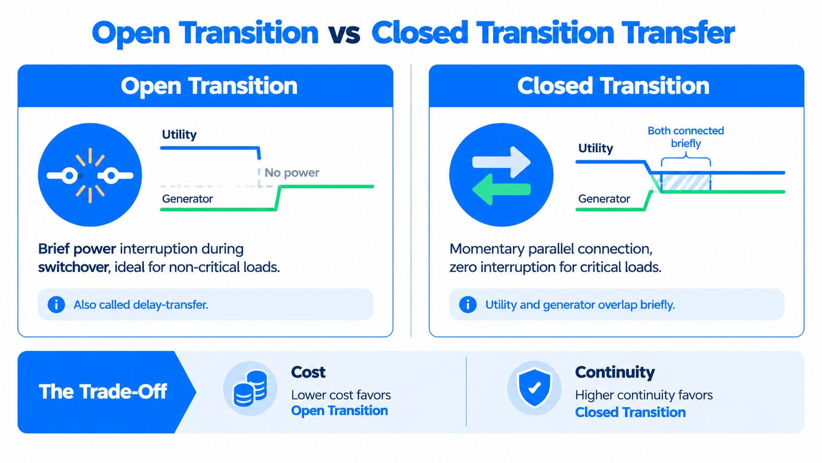
Consideration | Open transition | Closed transition |
|---|---|---|
Source action | Breaks from one source before making the other | Briefly overlaps sources before disconnecting the normal source |
Load experience | Short interruption during transfer | Little or no interruption when correctly synchronized |
Generator protection | Simpler source separation | Requires coordination for momentary paralleling |
Typical fit | Homes, offices, and non-critical loads | Critical facilities and sensitive processes |
Project trade-off | Lower complexity and easier service | Greater design and control requirements |
The smoother transfer is not always the better transfer. Choose closed transition because the load requires it, not because a shorter interruption sounds impressive on a quotation.
ATS Types and Rating Considerations
Choose an automatic transfer switch ATS from the electrical system outward. Confirm source voltage, phase arrangement, load current, available fault current, neutral configuration, installation location, and transition method before selecting a model. A generator's nameplate capacity does not establish that an ATS is suitable. The switch must also withstand the fault duty at its installation point and coordinate with upstream overcurrent protection.
Common construction types
A contactor-type ATS is common in residential and light-commercial standby systems. Its compact construction and relatively simple control scheme can suit these installations, provided the voltage, current, fault-duty, and service requirements match. Larger systems may use motorized switching mechanisms, molded-case designs, power-frame equipment, or solid-state transfer equipment. The added complexity only makes sense when the installation requires higher current capacity, faster operation, a different duty cycle, or specific maintenance characteristics.
Voltage and frequency ratings must match both sources. Low-voltage utility-to-generator product families commonly cover systems up to 600 Vac at 50/60 Hz and may carry a UL 1008 listing, as outlined in low-voltage ATS specifications. Larger commercial equipment can support continuous currents from 3,000 A to 5,000 A. Its short-circuit withstand and close-on ratings may reach 100 kA on a time basis or 200 kA with specified fuse classes. Those figures only help when they exceed the available fault current and align with the upstream protective devices.
Rating checklist
ATS Type | Typical Use | Current Range | Key Advantage |
|---|---|---|---|
Contactor-type ATS | Residential and light-commercial standby systems | Application-dependent, with low-voltage families up to 600 Vac | Compact construction and relatively simple wiring |
Motorized or molded-case ATS | Commercial distribution and larger standby systems | Selected to match the service and protected load | Broader configuration and protection options |
Power-frame ATS | High-current commercial and industrial systems | Commercial units may cover 3,000 A to 5,000 A continuous current | Handles substantial service capacity and fault-duty requirements |
Solid-state transfer equipment | Loads requiring very rapid electronic switching | Determined by the equipment and system design | Fast switching without conventional mechanical transfer movement |
Market size does not replace engineering
Market research describes adoption, not suitability for a particular property. One automatic transfer switch market report valued the global category at USD 943.78 million in 2025 and projected USD 1.52884 billion by 2034, with a projected 5.51% CAGR. It also reported that automatic switches represented about 68% of the broader transfer-switch market.
North America is a major demand center. A wider transfer-switch market analysis reported 39.10% of global share for North America in 2025 and stated that automatic switches represented 84.34% of that broader regional market. That demand reflects generator-backed residential, commercial, healthcare, infrastructure, and data-center installations. It does not determine whether a particular ATS fits a panel. Fault coordination, source ratings, neutral configuration, and load compatibility still decide whether the installation will operate safely.
Installation and Compatibility Essentials
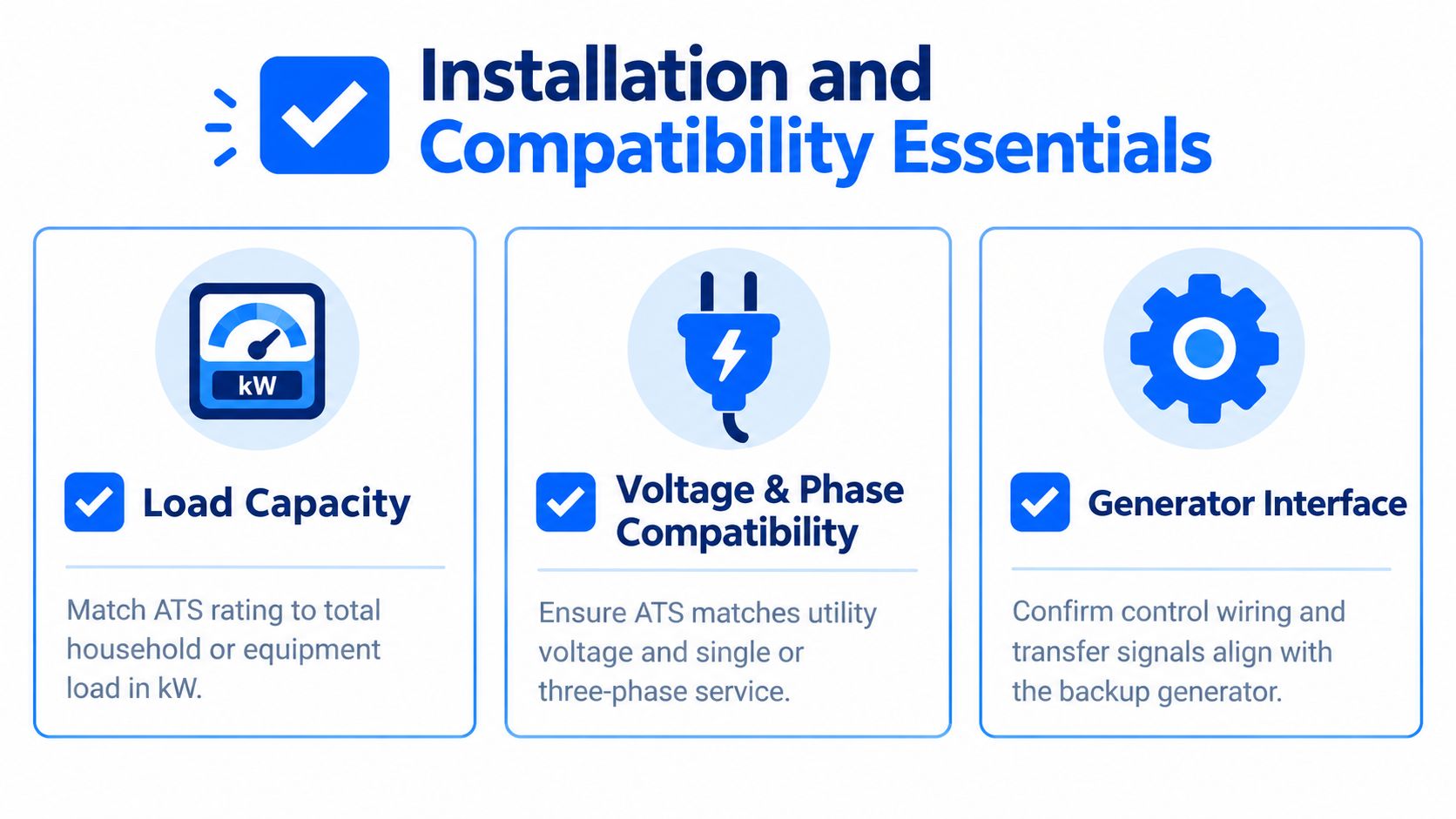
Most ATS problems appear after purchase because the switch, generator, service equipment, and protected loads were treated as separate products. They aren't separate in operation. The control signal, source sensing, overcurrent protection, neutral arrangement, and load connections must work as one system under the conditions set by the local utility and electrical code.
Check the panel before ordering
Start at the service equipment. Confirm the service rating, bus capacity, available breaker positions, feeder arrangement, neutral and grounding configuration, and whether the proposed ATS is service-rated or intended for downstream installation. A generator may have enough capacity for selected circuits, but that doesn't make every panel arrangement acceptable.
Load selection also matters. A whole-house system and a critical-loads panel solve different problems. If the generator can't support large heating, cooling, cooking, or motor loads at the same time, the design may need load management or a deliberately limited protected panel.
Verify the control interface
The ATS must communicate correctly with the generator controller. The start signal, run status, source sensing, warm-up delay, retransfer delay, and shutdown command all depend on correct control-circuit wiring and configuration. A generator that starts manually can still fail to transfer automatically if the control conductors are miswired, the terminal assignments don't match, or the controller doesn't receive the expected signal.
Manufacturer troubleshooting guidance identifies both generator output and control-circuit integrity as causes of failed transfer. Breaker position, warm-up timing, and transfer-circuit voltage can also prevent a correctly installed system from switching or can cause it to return to utility power too early. A practical automatic transfer switch installation checklist should therefore cover the complete path from utility source to generator controller to protected panel.
Plan maintenance at installation
An ATS needs periodic testing, not just a successful commissioning day. Exercise cycles, visual inspection, control checks, and contact inspection help identify a mechanism that doesn't move freely or a control circuit that has degraded. Testing should confirm both directions of transfer, generator startup, stable source sensing, retransfer, and shutdown.
Modern product literature highlights fewer connection points, faster in-phase transition, and factory-installed surge protection as reliability improvements. These features can reduce wiring complexity and improve transient protection, but they don't compensate for poor terminations, incorrect settings, inadequate conductor sizing, or an unsuitable fault rating.
The failure question to ask isn't only, “Will it carry my load?” Ask, “What exact condition makes it start, transfer, retransfer, and stop, and how will we test each one?”
Why Specification Errors Cause Real Failures
A low purchase price offers little value if the ATS fails during the first serious outage. A complaint such as “the generator works, but the house didn't transfer” usually points to a mismatch between the switch and the electrical conditions at the installation.
Four mistakes with predictable consequences
Insufficient fault-current rating can damage the switch or leave it unable to perform as required. The ATS must withstand and close into the prospective fault current available at its installation point. Its rating also has to coordinate with upstream breakers or fuses. If the available fault current exceeds the selected rating, the project may require a different switch construction, revised protective devices, or other work that was absent from the original quote.
A transfer delay that's too short can connect the load before the generator has reached stable voltage and frequency. The engine may be running while its output remains outside the acceptable range. Sensitive controls can trip, motors can start poorly, and the generator can receive a difficult step load.
A voltage or phase mismatch can prevent the ATS from recognizing the alternate source as usable. The generator output must match the ATS sensing arrangement. Otherwise, the switch may refuse to transfer, initiate repeated start attempts, or leave selected circuits without power.
Poor coordination with overcurrent protection can expose the ATS to excessive fault energy or cause nuisance operation. Review the switch rating, breaker settings, conductor protection, and available fault current as one system. Selecting each item independently is how compatibility problems reach the jobsite.
Faster isn't automatically safer
The timing requirements discussed in UL 1008 transfer performance guidance exist because a transfer switch must control how sources connect to a load. Cutting every delay does not necessarily improve performance. The generator needs time to establish stable output, while the utility source needs time to prove that it has returned reliably.
Retransfer needs the same discipline. If the ATS returns to utility power after voltage briefly reappears, another disturbance can make the load move between sources or put the generator through unnecessary cycles. Set the delays according to the generator, utility conditions, and equipment being protected.
Before accepting a quote, request the ATS model, transition type, voltage and phase rating, continuous-current rating, short-circuit rating, control wiring plan, and proposed delay settings. Ask the installer to explain how those values coordinate with the service equipment and upstream protection. This review often exposes a panel or fault-rating conflict before equipment is ordered.
Maintenance protects that investment. A documented automatic transfer switch maintenance plan should include operational testing and inspection, so a failed mechanism, control circuit, or sensing function is found before an outage demands a transfer.
Choosing the Right ATS Solution
A sound selection process starts with the loads, not the product label. List the circuits that must remain available, identify motors and other difficult starting loads, and decide whether a brief interruption is acceptable. That decision usually points toward open transition for general backup or a more specialized arrangement where continuity requirements justify added complexity.
Use this decision sequence
Analyze the load. Establish which circuits are essential and whether the generator can start and carry them together. Include heating, cooling, pumps, refrigeration, controls, and equipment with sensitive electronics.
Match the source arrangement. Confirm the utility voltage, phase configuration, generator output, neutral treatment, and grounding method. Don't assume that two products with similar ampere labels are interchangeable.
Select the transition method. Use open transition when a controlled interruption is acceptable. Consider closed transition or another specialized design only when the load and facility operation require it.
Confirm protection and certification. Review continuous current, available fault current, upstream protective devices, enclosure conditions, and UL 1008 listing where applicable.
Inspect the installation path. Verify the panel, service equipment, conductor routes, control terminals, disconnects, and local permitting requirements before equipment arrives.
Commission the complete system. Test utility failure, generator startup, transfer, load operation, utility restoration, retransfer, and shutdown. Record the settings so future maintenance doesn't rely on guesswork.
Why local experience helps
Southeastern Pennsylvania homes and businesses can have very different service layouts, utility requirements, panel conditions, and backup priorities. A contractor who evaluates the existing installation can identify whether the project needs an ATS, a service upgrade, a dedicated critical-loads panel, load management, or a different backup architecture.
Amp'd Energy Solutions provides generator and backup-power integration, automatic transfer switch planning, electrical service upgrades, and related battery backup work for homes and businesses in Southeastern Pennsylvania. Its family-operated team also provides Tesla-certified installation capabilities for applicable energy projects, so customers can coordinate related electrical work through one regional contractor.
The cost of an automatic transfer switch installation depends on more than the switch itself. Service changes, panel work, conductor routing, generator controls, permitting, testing, and the required protection scheme can all affect the project. A detailed site assessment is more useful than comparing equipment prices without knowing what the installation requires.
The goal is simple: when the next storm arrives, the system should detect the outage, start the backup source, transfer the intended loads, and return to utility power without unsafe manual intervention. Proper specification and installation are what make that sequence dependable.
If you're planning generator backup, battery storage, or an ATS upgrade, Amp'd Energy Solutions can assess your electrical service, confirm equipment compatibility, and coordinate a code-conscious installation in Southeastern Pennsylvania. Contact the team to review your loads, panel, generator interface, and transfer requirements before you purchase equipment.
Comments